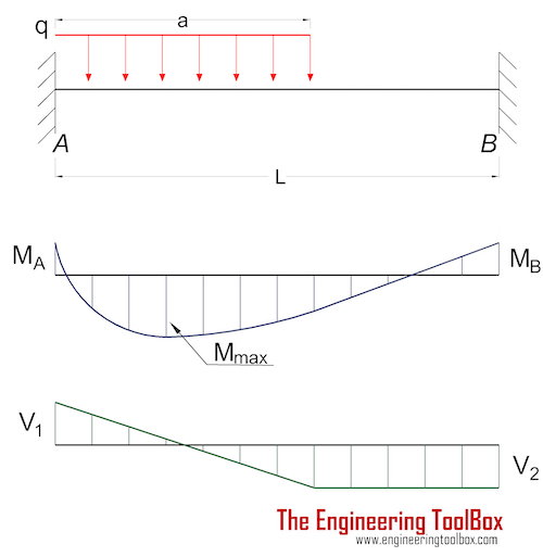
Beam Fixed at Both Ends Uniformly Distributed Load
Question 1 A simply supported composite beam 3 m long carnes a uniformly distrbuted load of A. Enter the email address you signed up with and well email you a reset link.
Beams Fixed At Both Ends Continuous And Point Loads
Fixed beam with partially distributed linearly varying load PDVL.
. The face of the beam that is parallel to the yz-plane and located at x 0 is rigidly fixed ie zero displacements in x- y- and z-directions. Cantilever beam-uniformly distributed load 20. The edges of a platform that are more than 14 inches away from a sturdy continuous vertical surface such as a building wall or a sturdy continuous horizontal surface such as a floor or a point of access.
In the following examples clockwise. Fixed beams are not allowed the vertical movement or rotation of the beam. At supports bottom the part experiences compression while the top part experiences tension just opposite the moment develop at the centre.
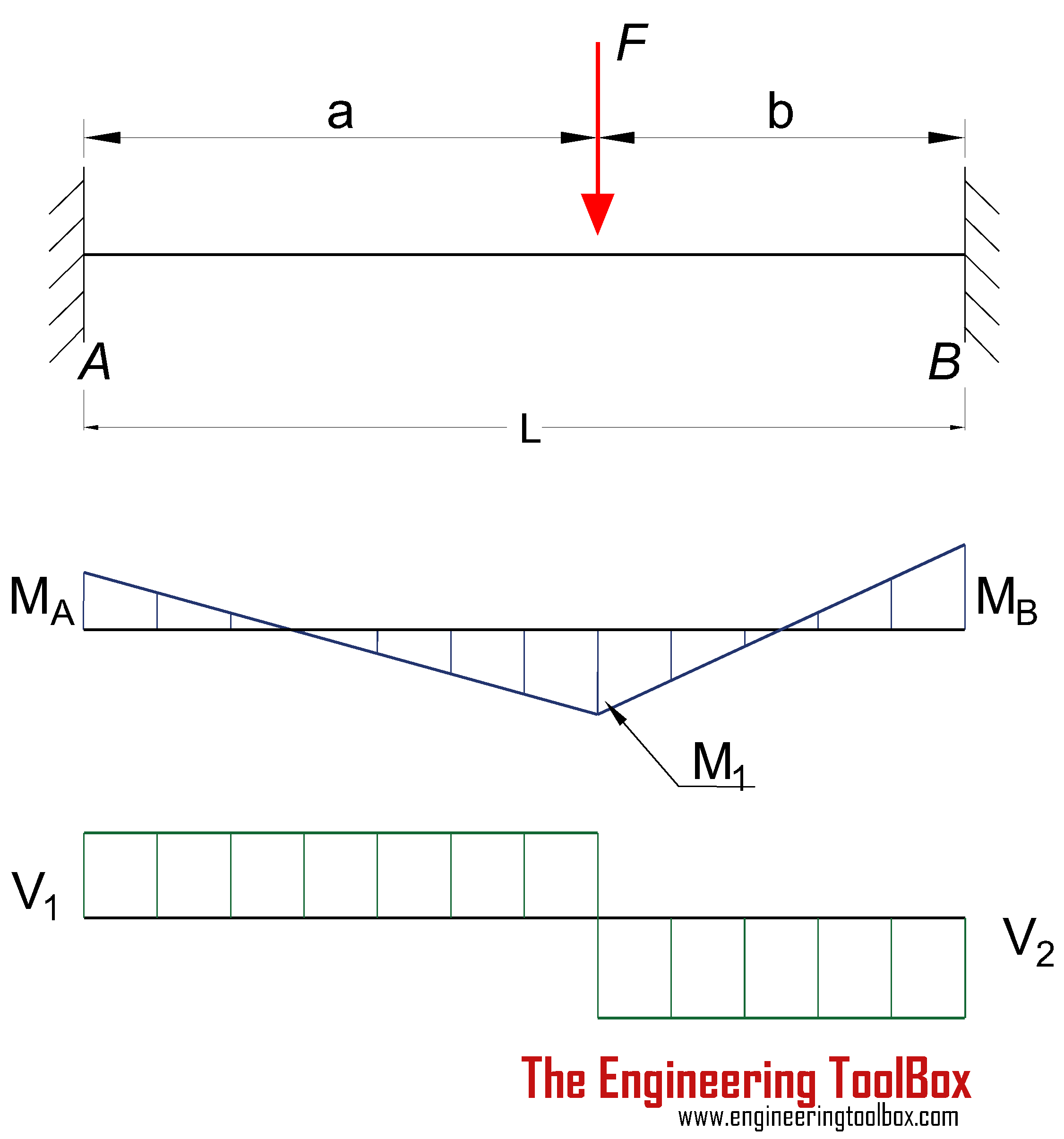
The beam is supported at each end and the load is distributed along its length. M x q x L - x 2. Beam fixed at both ends-concentrated load at center.
This load shall not be reduced. A simply supported beam will have moment reaction at both ends to be 0 and will have vertical reactions at both ends. Fixed beam with udl in any other position needs to be input with appropriate distances.
The face that is parallel to the yz-plane and located at x L has a uniformly distributed force acting on it. Beams - Fixed at Both Ends - Continuous and Point Loads. A beam ABC 10m long fixed at ends A and B is continuous over joint B and is loaded as shown in Fig.
For a simply supported beam with uniformly distributed load for full length will have distance a 0 and distance b L. A simply supported beam AB 11 m has a hollow rectangular cross-section with 13 cm as width 22 cm as depth and inner thickness as 2 cm is subjected to a point load of 9 N 6 N acting at C and D respectively and a uniformly distributed load UDL of 9 Nm starts from mid-span and ends at the right support of the beam. The partition load shall be not less than a uniformly distributed live load of 15 psf 072 kNm 2.
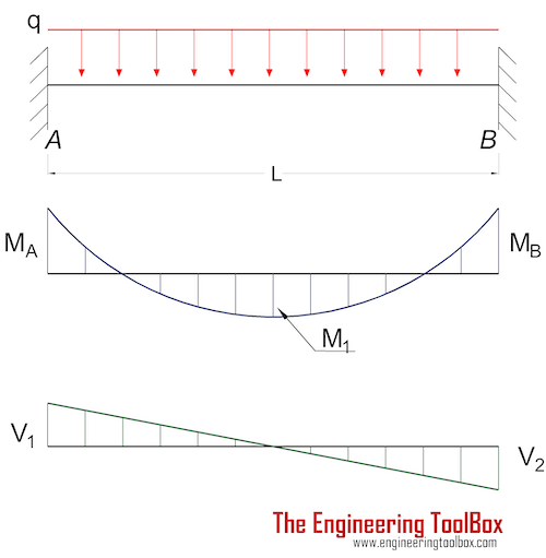
M A moments at the fixed end A Nm lb f ft q uniform declining load Nm lb f ft M B - q L 2 30 3b where. BEAM FIXED AT BOTH ENDS - UNIFORMLY DISTRIBUTED LOADS. Slope at both end will not be 0.
Open Sides and Ends. R support forces at the fixed ends N lb f Beam Fixed at Both Ends - Uniform Declining Distributed Load Bending Moment. Fixed beam with udl spanning entire length will have distance a to be equal to zero and distance b should be equal to length of beam.
For plastering and lathing operations. M A - q L 2 20 3a where. The fixed end moments are reaction moments developed in a beam member under certain load conditions with both ends fixed.
A beam with both ends fixed is statically indeterminate to the 3rd degree and any structural analysis method applicable on statically indeterminate beams can be used to calculate the fixed end moments. Free Isolated foundation calculation imperial Free calculation no login required. Calculation of beam internal forces shear force bending moment and deflections metric beam fixed loads load cases forces deflection Open calculation sheet.
In this beam no bending moment will produce. Treating each span as a fixed beam the fixed end. 2 For applicable tests specified in S75a S77 S78 and S79 vehicle weight is lightly loaded vehicle weight with the added weight except for the roll bar structure allowed for trucks and buses with a GVWR greater than 10000 pounds distributed in the front passenger seat area in passenger cars multipurpose passenger vehicles and trucks and in the area adjacent to the.
The moment developed at support is called a negative moment while it is called a positive. A simply supported beam is the most simple arrangement of the structure. Helipads shall be designed for the following live loads.
40 psf 192 kNm 2. Cantilever beam-load increasing uniformly to fixed end. Fig1 Formulas for Design of Simply Supported Beam having.
All units can be changed by the user. Both ends of the beam are rigidly fixed with supports. The moment in a beam with uniform load supported at both ends in position x can be expressed as.
All other faces of the beam are unconstrained and unloaded. Calculate the maximum bending moment. Bläi 4 For a beam as shown in the below figure the deflection at the free end are 8 kN 6kNm A_c.
A beam that is fixed at both ends is called a fixed beam. Beam Supported at Both Ends - Uniform Continuous Distributed Load. Let the shearing force at the section x be F and at Similarly the bending moment is M at x and If w is the mean rate of loading of the length then the total load is acting approximately exactly if uniformly distributed through the centre CThe element must be in equilibrium under the action of these forces and couples and the following equations can be.
When the beam is fixed at both ends column-beam junction moment develop at the centre and on each supports. A platform suspended from needle beams. A single concentrated live load Larea of 45 inches by 45 inches 114 mm by.
Fixed beam carrying half udl will have the distance a0 or a L2 and distance bL2 or bL respectively for two cases. Beam fixed at one end free to deflect vertically but not rotate at other-uniformly distributed load. Beam fixed at both ends-concentrated load at any point 18.
A uniform live load L as specified in Items 11 and 12. Beam Fixed at Both Ends Uniformly Distributed Load Beam Fixed at Both Ends Concentrated Load at Center Beam Fixed at Both Ends Concentrated Load at Any Point Continuous Beam Two Equal Spans Uniform Load on One Span Continuous Beam Two Equal Spans Concentrated Load at Center of One Span Continuous Beam Two Equal Spans. Calculation of the maximum pressure under foundation imperial.
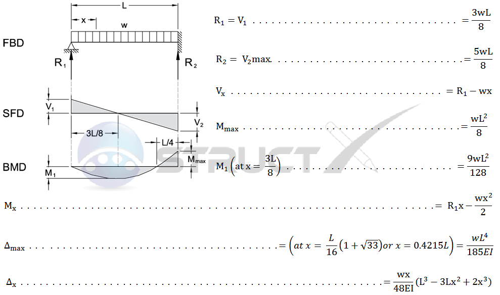
The calculator below can be used to calculate maximum stress and deflection of beams with one single or uniform distributed loads. The beam has constant EI for both the spans. 3-218 DESIGN OF FLEXURAL MEMBERS Table 3-23 continued Shears Moments and Deflections 15.
Beam fixed at both ends-uniformly distributed loads 16. A Fixed end moments. Fixed beams are only under the shear force and are generally used in the trusses and like other structures.
60 psf 287 kNm 2. Beam Fixed at Both Ends metric Free calculation no login required. Also sketch the deflected shape of the beam.
AMERICAN WOOD COUNCIL w R V V 2 2 Shear M max Moment x 7-36 A ab c x R 1 R 2 V 1 V 2 Shear a R 1 w M max Moment wb 7-36 B Figure 1 Simple BeamUniformly Distributed Load. Consequently they are free. The following table presents the formulas describing the static response of the fixed beam with both ends fixed under a partially distributed trapezoidal load.
Using the slope deflection method compute the end moments and plot the bending moment diagram. A simply supported beam cannot have any translational displacements at its support points but no restriction is placed on rotations at the supports.
Beams Fixed At Both Ends Continuous And Point Loads
Fixed End Beam Udl

Beam Fixed At Its Ends 2 2 1 Fixed End Moments Figure 2 A Shows The Download Scientific Diagram
Beams Fixed At Both Ends Continuous And Point Loads
No comments for "Beam Fixed at Both Ends Uniformly Distributed Load"
Post a Comment